Arduino Inline Assembler Coding

Following on from the last experiment with the digital I/O pins, which achieved an output frequency of 95 KHz from the Arduino (and a similar rate from the BeagleBone Black), I found this Youtube video about inline assembler, which is a feature provided by the Arduino software. Using the inline assembler enables the slow I/O libraries of the Arduino to be bypassed, which leads to higher speeds.

There are two instructions which enable an I/O pin to be toggled:

  • SBI – set a bit on an I/O port (set it to one or a high voltage)
  • CBI – clear a bit on an I/O port (set it to zero or a low voltage)

Both instructions have the same format. Two values are supplied, separated by a comma. The first value is the port that is being used, and the second value is which bit on that port is being used. For example:

  • SBI 0x5,5 – set bit #5 of port 5.

The following table shows the combinations of ports and bits for each digital I/O pin on my Arduino Nano. I/O pins 0 and 1 are reserved for the serial I/O port.

Arduino ports and pins data

Arduino ports and pins data

In my previous example, I chose I/O pin 8, here port 0x05 and bit 0. So the Arduino code becomes this:

void setup() {
// initialize digital pin 8 as an output.
pinMode(8, OUTPUT);
}

// the loop function runs over and over again forever
void loop() {
//digitalWrite(8, HIGH); // turn the LED on (HIGH is the voltage level)
//digitalWrite(8, LOW); // turn the LED off by making the voltage LOW

asm(“sbi 0x05,0”);
asm(“cbi 0x05,0”);
}

I  haven’t tried to recode the pinMode instruction, because it only runs once, and so there would be not benefit in doing so. The previous digitalWrite instructions have been commented out.

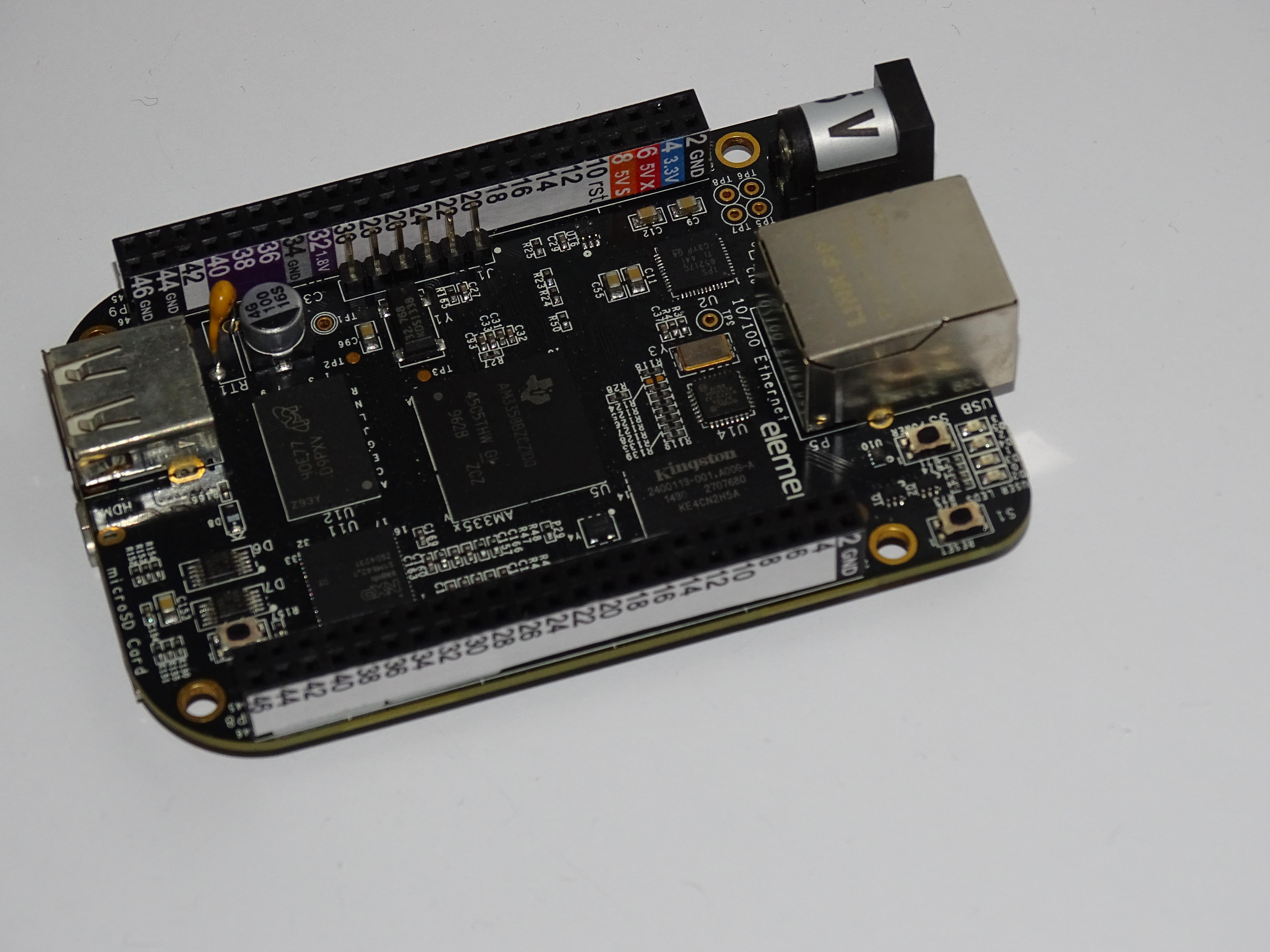
The LED board was reattached, and the Analog Discovery oscilloscope was used to record the waveform.

Arduino inline 1

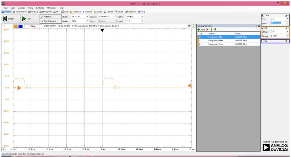
The ‘SBI’ instruction ran in approximately 140 nanoseconds, which corresponds to 2 clock ticks of the Arduino Nano’s processor (16MHz). However, the whole cycle took 1000 nanoseconds, corresponding to 16 clock ticks. This was the time it took to return from the ‘loop’ function and return, in addition to the two clock ticks to run the ‘CBI’ instruction.

A second experiment was done, but this time with an assembler loop within the ‘loop’ function. The ‘start:’ is a label which identifies a location in the code. ‘JMP’ means go to that location.

void setup() {
// initialize digital pin 8 as an output.
pinMode(8, OUTPUT);
}

// the loop function runs over and over again forever
void loop() {
//digitalWrite(8, HIGH); // turn the LED on (HIGH is the voltage level)
//digitalWrite(8, LOW); // turn the LED off by making the voltage LOW

asm(“start:”);
asm(“sbi 0x05,0”);
asm(“cbi 0x05,0”);
asm(“jmp start”);
}

Arduino inline 2

The data is not being clocked at twice the rate, corresponding to a frequency of 2.3MHz, a period of approximately 430 nanoseconds, or seven clock ticks:

  • SBI for two clock ticks
  • CBI for two clock ticks
  • JMP for three clock ticks

As an aside, this is 20 times faster than the BeagleBone Black was able to achieve, indicating how much faster it is to access the I/O directly, even with a processor running 60 times slower (16MHz clock versus 1000 MHz clock).

Here is the Atmel datasheet for the processor in the Arduino range, including the Arduino Nano. The port details are given in section 14.4. The instruction set is given in section 37.

Coding GPIO on Beaglebone Black and Arduino

The Beaglebone Black has a C++ compiler called ‘g++’. I wrote a C++ class library to control the GPIO pins of the Beaglebone Black, and compiled the library (together with a test routine) using g++. The code was written using Leafpad on the Beaglebone Black, using VNC to show the BeagleBone Black desktop on my Windows 8 PC.

The class library contains a constructor, GPIO::GPIO, which create (exports) a file system for the required GPIO pin, and a destructor GPIO::~GPIO, which removes (unexports) the file system again.

The direction and value of the pin can be set using SetDir and SetValue. The value of the pin is set by opening the file-system, writing the value, and closing the file-system again. This is quite slow, and so a faster method is to keep the file-system open during writes, with streamOpen – streamWrite – streamClose.

// Class for controlling GPIO

#include
#include
#include
#include
using std::string;
using std::ofstream;
using std::ostringstream;
using std::cout;
using std::endl;
# define GPIO_PATH “/sys/class/gpio”

class GPIO {
public:
GPIO(int group,int pin);
virtual ~GPIO();
void debug(void);// slow control of pins
virtual void SetValue(int value);
virtual void SetDir(string pindir);// fast control of pins;
virtual int streamOpen();
virtual int streamWrite(int value);
virtual int streamClose();

private:

int internal_gpio;
string gpio_path;
string export_path;
string value_path;
string dir_path;
string Int2String(int a);
ofstream gpio_stream;
};

string GPIO::Int2String(int a)
{
ostringstream temp;
temp << a;
return string(temp.str());
}

GPIO::GPIO(int group,int pin) // so GPIO 1_17 would be GPIO(1,17)
{
ofstream fs;// figure out where we are
internal_gpio=group*32+pin;
gpio_path=string(GPIO_PATH)+”/gpio”;
gpio_path=gpio_path+Int2String(internal_gpio);
value_path=gpio_path+”/value”;
dir_path=gpio_path+”/direction”;// export pin
export_path=string(GPIO_PATH)+”/export”;
fs.open(export_path.c_str());
fs << Int2String(internal_gpio);
fs.close();
}

void GPIO::debug(void)
{
// debug code
cout << “Internal no. ” << internal_gpio << endl;
cout << “Export path: ” << export_path << endl;
cout << “GPIO path: ” << gpio_path << endl;
cout << “Direction: ” << dir_path << endl;
cout << “Value path: ” << value_path << endl;
}

GPIO::~GPIO()
{
ofstream fs;// unexport pin
export_path=string(GPIO_PATH)+”/unexport”;
fs.open(export_path.c_str());
fs << internal_gpio;
fs.close();
}

void GPIO::SetDir(string pindir)
{
ofstream fs;// set value, by writing to ‘value’
fs.open(dir_path.c_str());
fs << pindir;
fs.close();
}

void GPIO::SetValue(int value)
{
ofstream fs;// set value, by writing to ‘value’
fs.open(value_path.c_str());
fs << value;
fs.close();
}

int GPIO::streamOpen()
{
gpio_stream.open(value_path.c_str());
}

int GPIO::streamWrite(int value)
{
gpio_stream << value << std::flush;
}

int GPIO::streamClose()
{
gpio_stream.close();
}

main()
{
long ll;GPIO newpin(1,17);
newpin.SetDir(“out”);
newpin.streamOpen();

for (ll=0;ll<10000000;ll++)
{
newpin.streamWrite(0);
newpin.streamWrite(1);
//newpin.SetValue(0);
//newpin.SetValue(1);
}

newpin.streamClose();
}

The LED board was connected again to the BeagleBone Black, together with the Digilent Analog Discovery oscilloscope.

BeagleBone Black, LED board, and Digilent Analog Discovery

BeagleBone Black, LED board, and Digilent Analog Discovery

Using ‘SetValue’, an output rate of 5 KHz is achievable. Opening and closing the file-system is very slow.

Slow BBB output

Individual write output

Using ‘streamWrite’, an output rate of 110 KHz is achievable. Keeping the file-system open makes for a much faster data transfer.

waveform

Stream write waveform

By way of comparison, the same experiment was done for the Arduino Nano. The Arduino Nano was inserted into a breadboard, so that my male-male connectors could be used. The blue cable was plugged into ground (GND), the orange wire into +5V (5V), and the green wire into GPIO pin 8 (D8).

Arduino Nano in breadboard

Arduino Nano in breadboard

The Arduino was connected to the LED board.

Arduino, LED board and Digilent Analog Discovery

Arduino, LED board and Digilent Analog Discovery

A simple program was downloaded to the Arduino, which turns the LED on and off as quickly as possible. The ‘Blink’ program was used as the basis for this, but now using pin 8 instead of the onboard pin 13 and LED.

// the setup function runs once when you press reset or power the board
void setup() {
// initialize digital pin 8 as an output.
pinMode(8, OUTPUT);
}

// the loop function runs over and over again forever
void loop() {
digitalWrite(8, HIGH); // turn the LED on (HIGH is the voltage level)
digitalWrite(8, LOW); // turn the LED off by making the voltage LOW
}

The resultant output runs at 95 KHz. This is quite slow for a 16MHz processor, but is similar to the BeagleBone Black which is a more advanced processor running at 1 GHz (1000 MHz). This shows just how expensive it is to run Linux on an embedded system.

Arduino

New Analog Discovery Tool

In the book ‘Exploring Beaglebone’ by Derek Molloy, he used a Digilent Analog Discovery tool to show oscilloscope waveforms. This tool is a two-channel digital oscilloscope, a 16-channel logic analyser, waveform generator and power supply, all connected to a PC using a USB cable. It appears to offer the best value for money. It cost $279 plus $58 delivery – $338 in total, or about £210.

The Analog Discovery comes with female connectors. For this reason, I have added a two-pin male connector to my LED board.This connector allows me to connect the Analog Discovery directly to the board.

LED board with new connector

LED board with new connector

GPIO circuit board

The first thing I’ trying is General Purpose Input Output, or GPIO. For these purposes, I have created a circuit board which I can attach to my Beaglebone Black. It consists of a green LED and a 220 ohm resistor (as per the Derek Molloy book). Because Beaglebone Black cannot safely drive an LED from the control pins, a MOSFET (a BS270) was added to the circuit board, and to protect the MOSFET gate from static, a 1 Mega-ohm resistor was connected between ground and the gate. (Actually, the gate appears to be reasonably resistant to static charge, anyway).

Circuit Layout

Circuit Layout

The circuit was tested using a breadboard, and then soldered onto a piece of stripboard. All of the components were of the traditional through-hole type. A label was printed out and put onto the front of the header block. I used UHU glue, which was a bad choice – PrittStick or similar works better and is less sticky.

DSC00091

Front of circuit board – header labelled (left to right) 7 – SYS_5V ; 1 – GND; CONTROL

DSC00080

Rear of circuit board

The board was connected as follows:

  • 5V to P9-7 5VS
  • GND to P9-1 GND
  • Control to P9-23 GPIO 1-17

The control drivers are provided in the Linux operating system as a collection of files. By writing to and reading from those files the control pin status is changed. You write to a file by using ‘echo’ and read from a file using ‘cat’. So, to operate the board certain steps must be followed:

  • Export GPIO 1-17
  • Set direction to output
  • Set value to one or zero

The Beaglebone Black has four groups of GPIO pins, numbered 0 through 3. Each group has 32 pins, numbered 0 through 31. The internal GPIO number is the GPIO group multiplied by 32, plus the pin number. Here, the internal GPIO number is 1 x 32 + 17, or 49. First, we export the pin.

cd /sys/class/gpio

echo 49 > export

cd /sys/class/gpio/gpio49

The two files (properties) that we are interested in are ‘direction’ and ‘value’. We set the direction to be ‘out’ and the value to ‘one’ – switching the MOSFET gate to high, and the LED on.

echo out  > direction

echo 1 > value

This then switches the LED on, and takes your eye out as a consequence – the LED is very bright!

LED board, control pin low

LED board, control pin low

LED board, control pin high

LED board, control pin high

New beginnings

I have decided to have a go at electronics. This seems like a good idea, since it is fun, practical, interesting and when I was at university I got good grades for it.

I’ve bought a Beaglebone Black development board and a Arduino Nano clone.I bought both because they work very differently, and I want to see how they compare. The Beaglebone Black board has a 1 GHz (1000 MHz) ARM processor, runs LInux, and has 92 connection points in two header blocks. The Arduino Nano has a 16 MHz processor of a much simpler design, has no operating system at all, only the smallest piece of built-in software to load my programs. Both connect to my PC using a USB cable, and make it easy to set them up.

I have also bought a copy of the book ‘Exploring Beaglebone’ by Derek Molloy, which explains clearly how to correctly attach things to Beaglebone Black. The board is a very expensive and sensitive beast. I also acquired some free stickers from Logic Supply. The instructions said to print on labels, but I obtained good results using regular paper and some glue. Because the connectors are now labelled, it is much harder to connect to the wrong pin.

Beaglebone Black with added header labels

Beaglebone Black with added header labels – header P9 in the background and P8 in the foreground

Finally, I downloaded a copy of the software ‘Putty’ and ‘WinSCP’ to control the Beaglebone Black. Using this software I can copy files between the PC and the Beaglebone Black, and also run a Linux terminal.